Table of Contents
What is Octoprint?
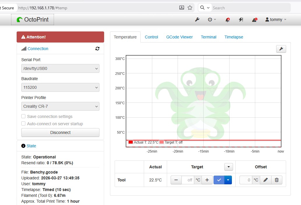
Octoprint is open-source software used to control and manage 3D printers. It can run on different platforms — a Raspberry Pi for example — and it connects directly to a 3D printer through USB. The main interface is accessed via a web browser. Octoprint supports live streaming and time-lapse video.
The 3D Printer
My first 3D printer was given to me. It was called NWA3D A5 but I know it goes by other names.
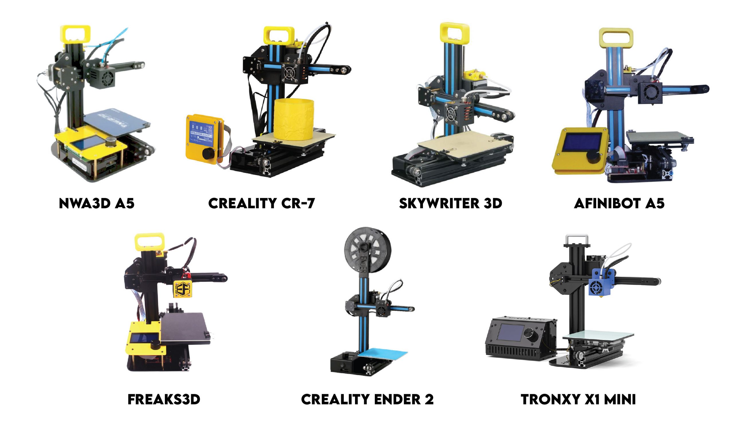
It’s a compact design. The mainboard is essentially an Arduino with an Atmega1284 microcontroller. It has a mini-USB port and if you connect it to a computer, you can program it just as you would any other Arduino. It runs open-source Marlin firmware.
The Camera
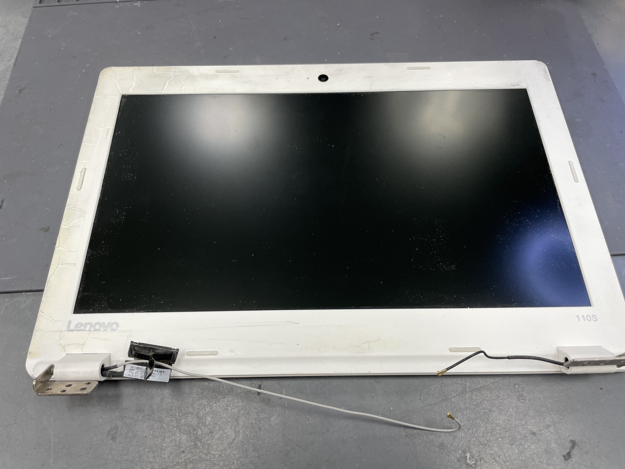
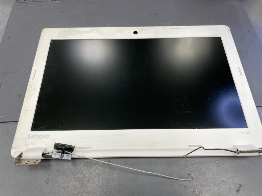
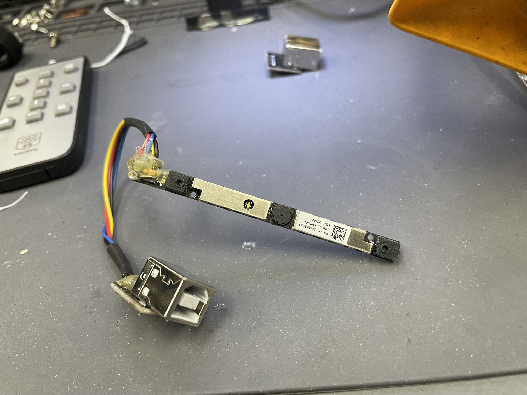
I salvaged the camera from a broken Lenovo IdeaPad 110s. The resolution is 640×360.
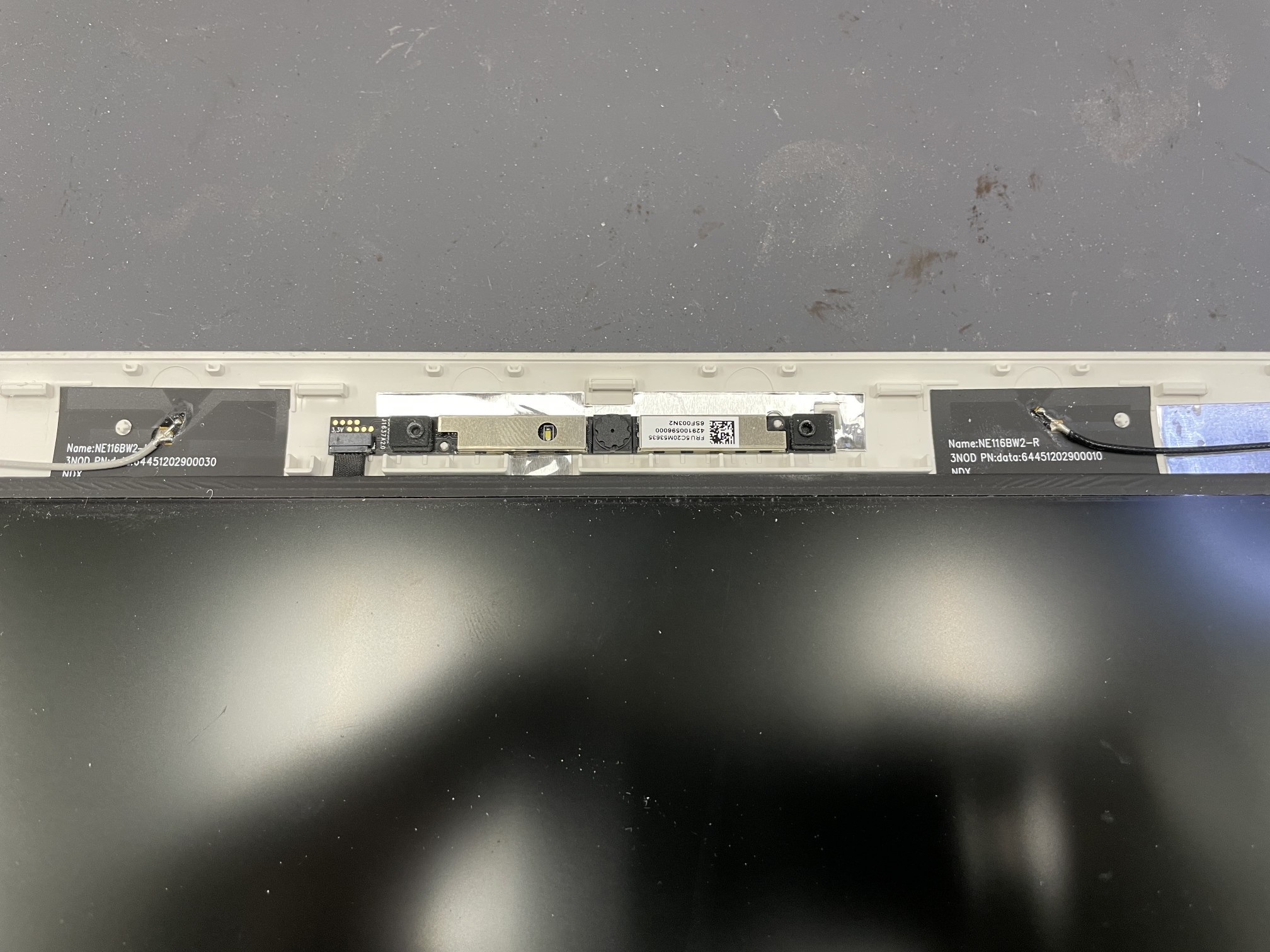
The bezel snaps off. The camera assembly is held in by double-sided tape. There is a small ribbon connector of the left side.
Camera Wiring and Pinout
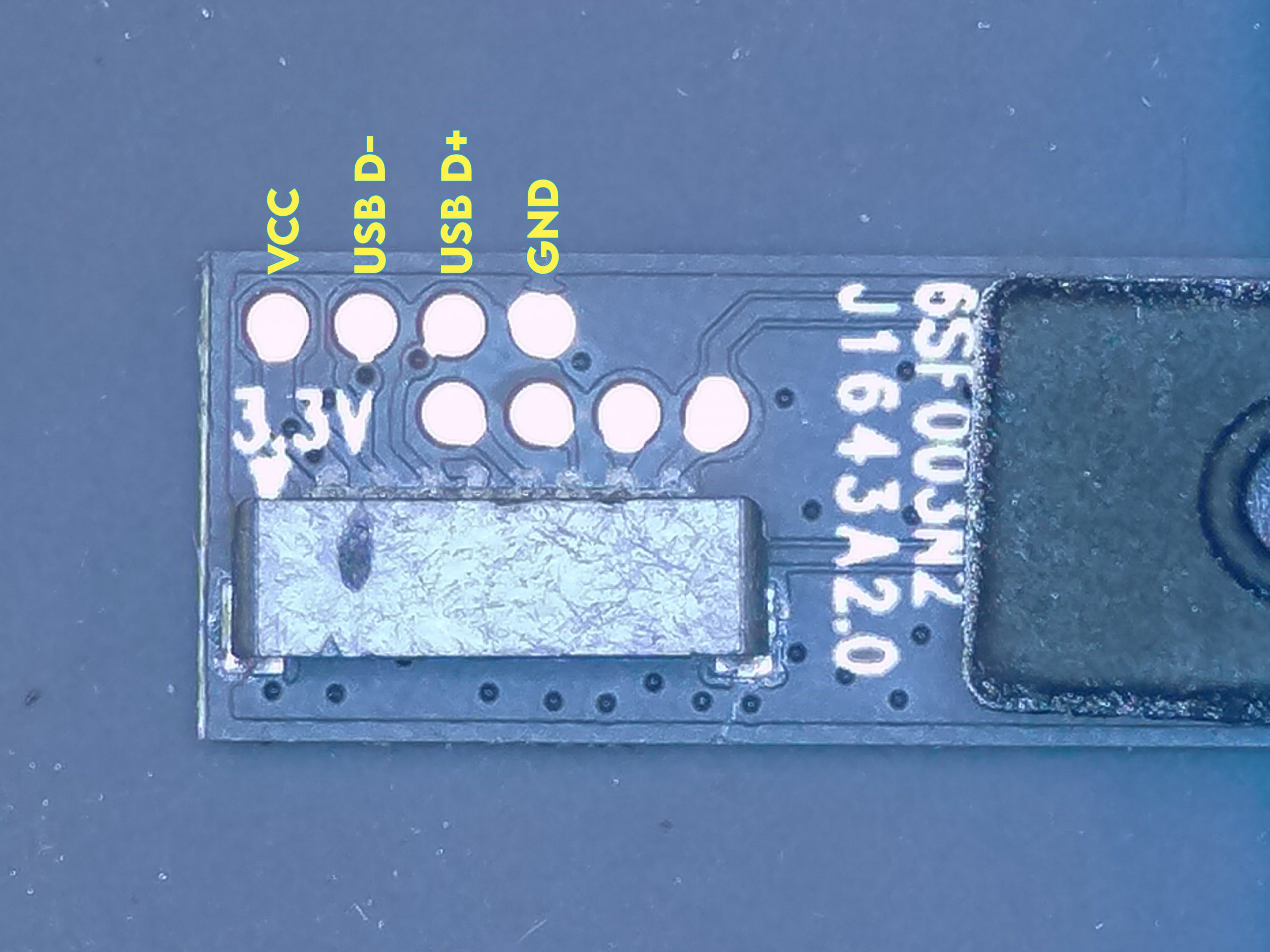
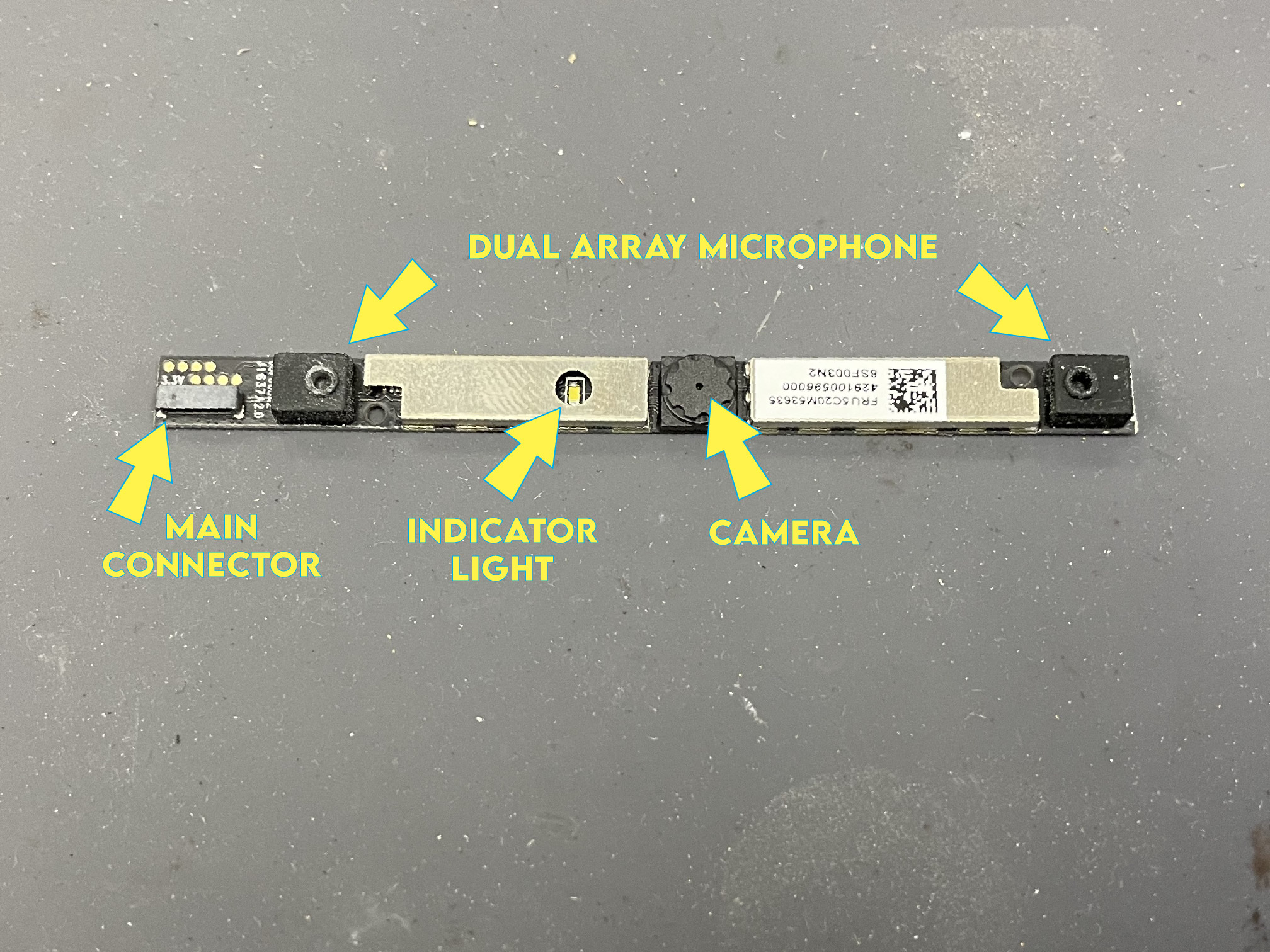
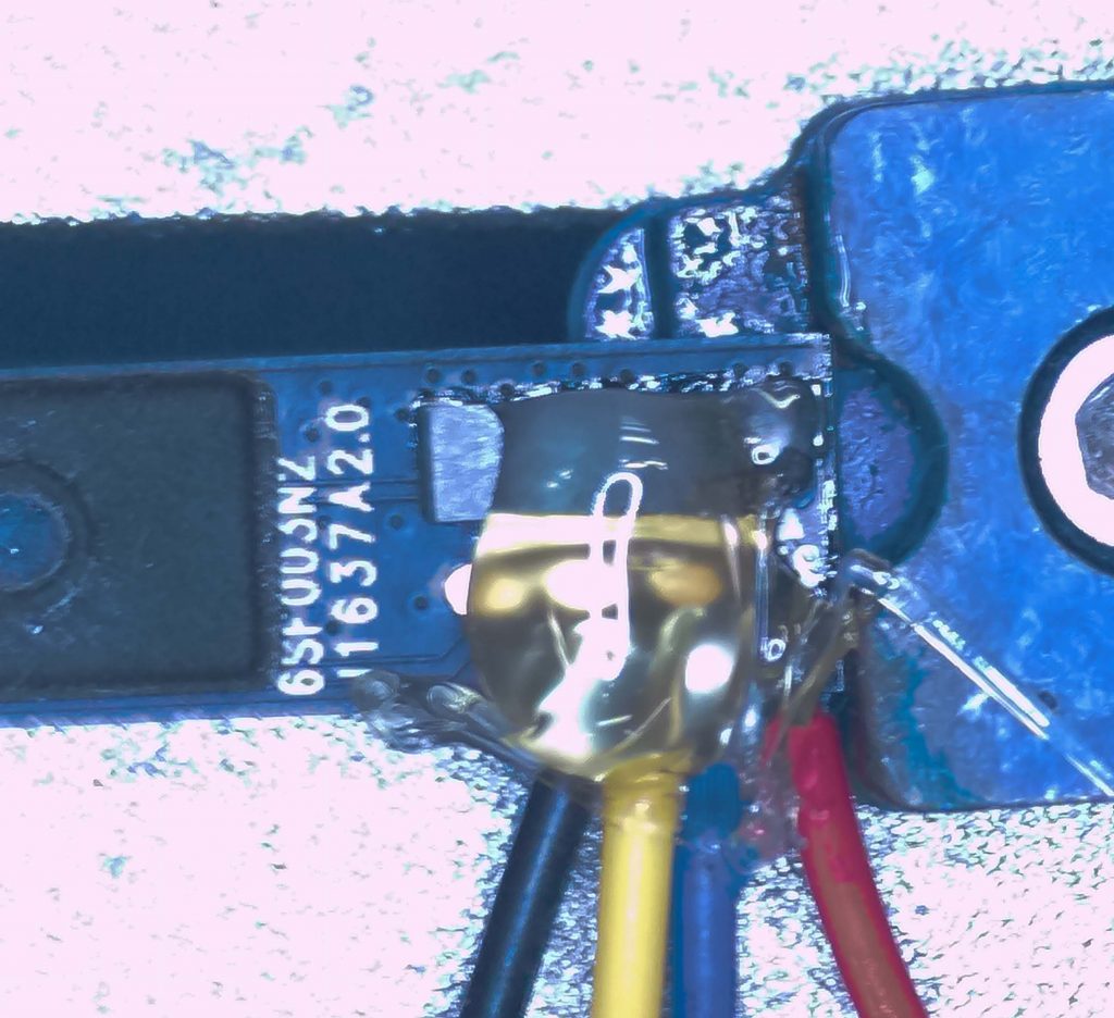
Most laptop cameras run on the USB bus. I was worried the connector pads would be too small to solder wires to, but luckily the PCB had larger pads next to the main connector.
The first pad is marked as 3.3V. I verified that the fourth pad was ground. It would make sense that the two pads in between are the differential pairs. I assumed it followed USB layouts I’ve seen in the past, so I guessed that pad #2 is D- and pad #3 is D+ (yes they were!). I assumed the other pads we for the mics so didn’t test them.
I took a chance with running 5V on the 3.3V pad. I have voltage regulators, but I convinced myself the components would be okay with 5V from USB.
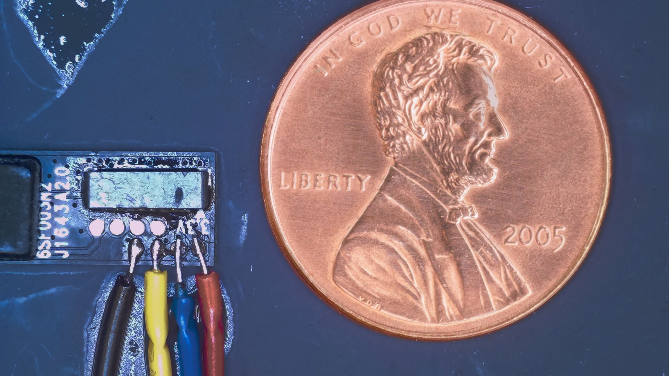
I have a magnifier camera and a “micro soldering pen” for fine work. I used 28AWG solid PVC wire, but you could go smaller. Silicone-wrapped wires might be better since they are more flexible and won’t put as much stress on the solder joints. There is a penny for reference. The wires may looked bridged, but it’s excess flux.
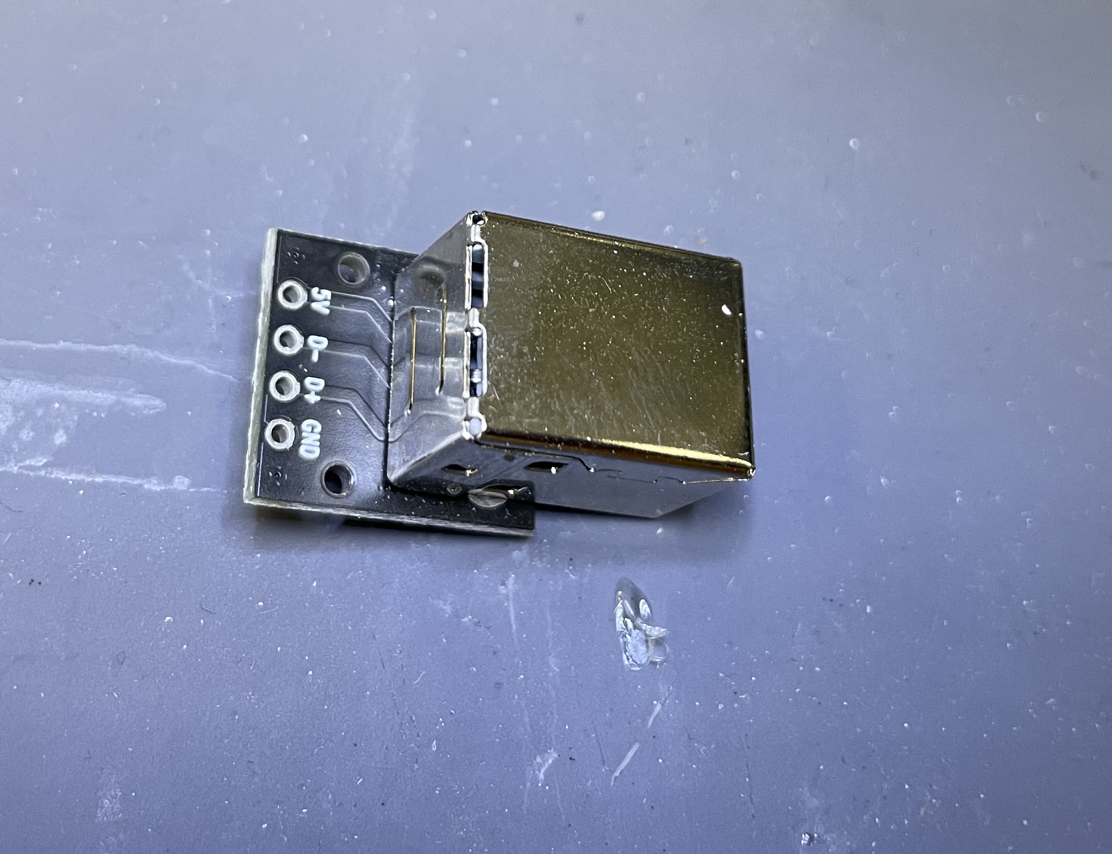
I soldered the other end to a USB-B breakout connector — I keep these on hand. You could also cut the USB-A end off any cable and solder it that way.
Testing
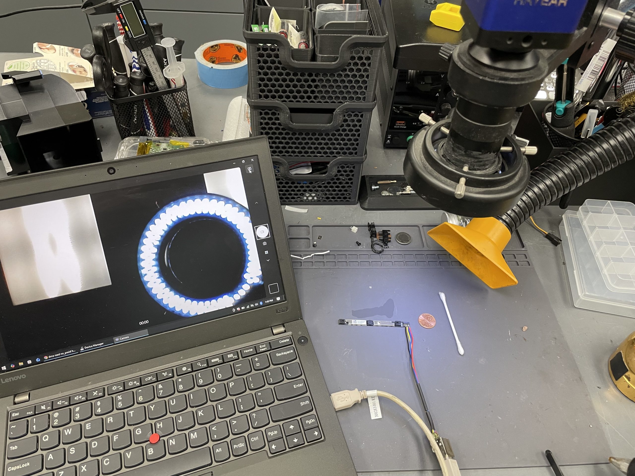
I plugged it into a Windows laptop and verified it worked with the Camera app. It also shows up on my Linux laptop as
ID 0bda:58e3 Realtek Semiconductor Corp. Lenovo EasyCamera
Once I verified everything worked, I covered the connection with hot glue so make sure the solder joints didn’t break away.
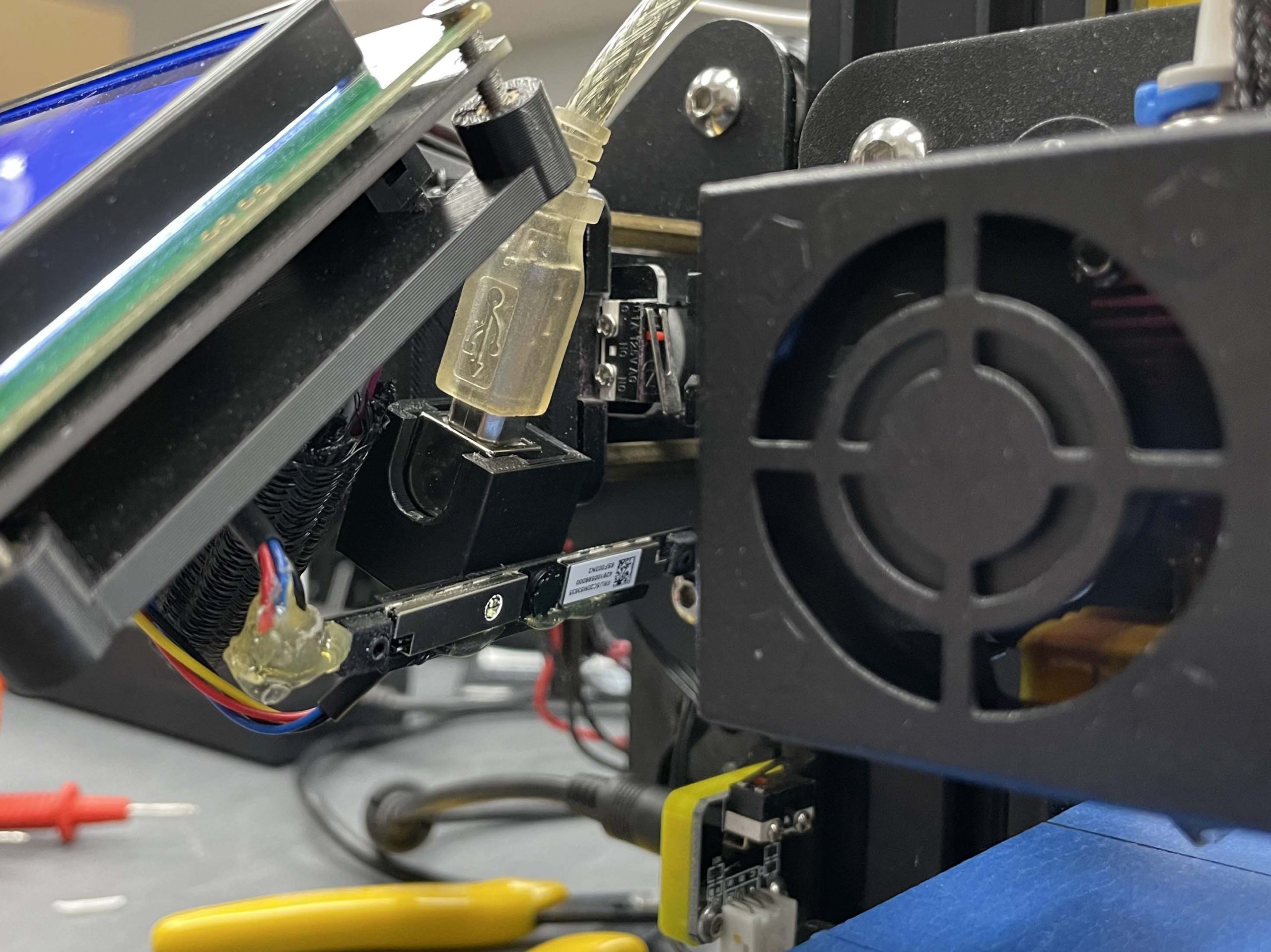
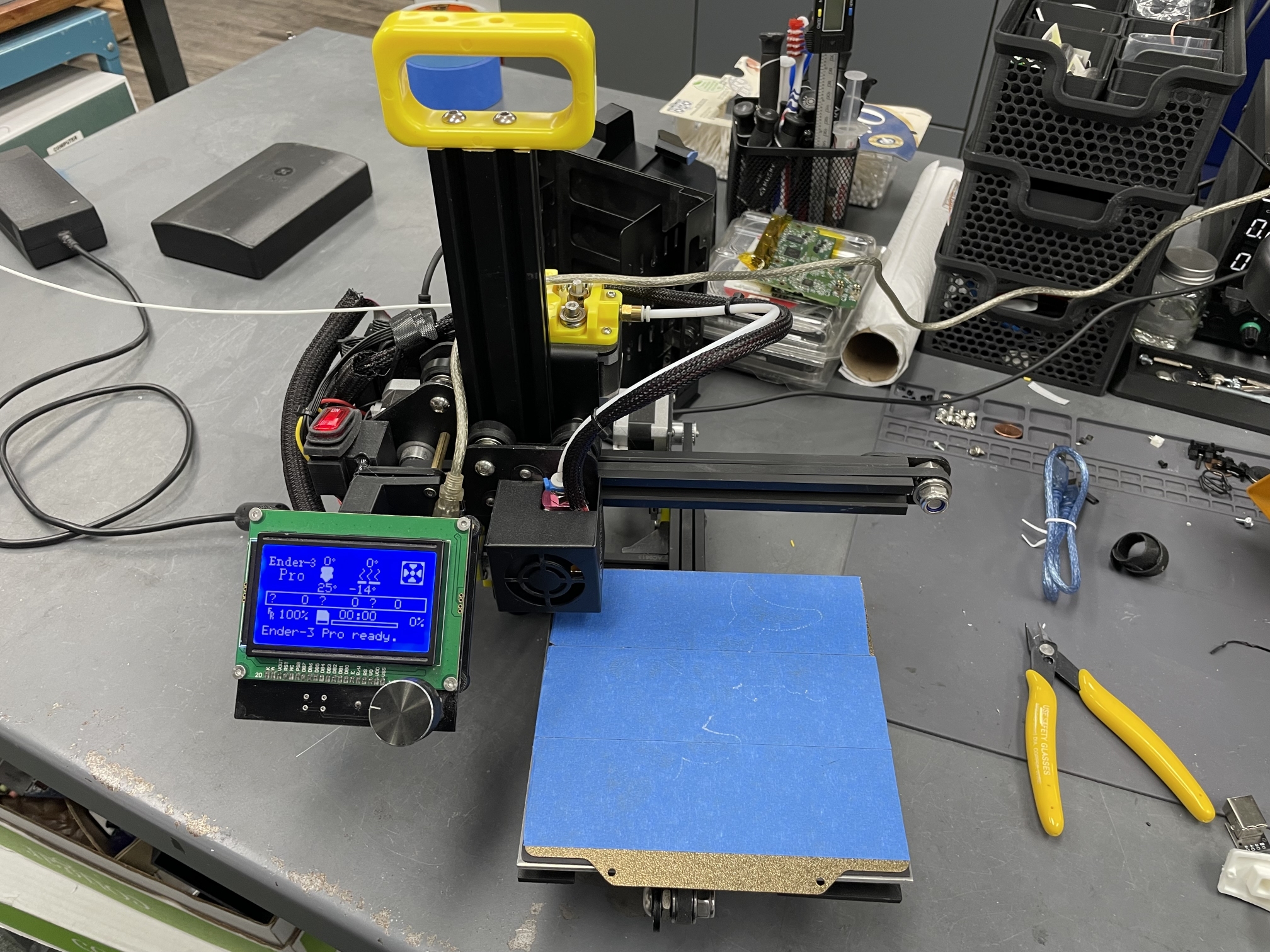
I 3D-printed a holder for it that screws directly to my 3D printer. The camera’s POV is fixed to Z-axis looking at the extruder.
I have Octoprint running on a Raspberry Pi 3b.
Time Lapse Footage
Yes. The print is a little rough. This was a 0.2mm layer height. 0.1mm looks much better.
Final Thoughts
I’ve thrown away so many broken laptops over the years. I salvage what I can but I never thought to save their cameras. You can get cheap Raspberry Pi cameras for less than $10, but I didn’t want to spend any money to upgrade this 3D printer.
Even though the resolution is low, the frame rate is so much better than the camera in my Bambu Lab P1S. But that has more to do with the compute power of a Raspberry Pi vs the P1S controller.